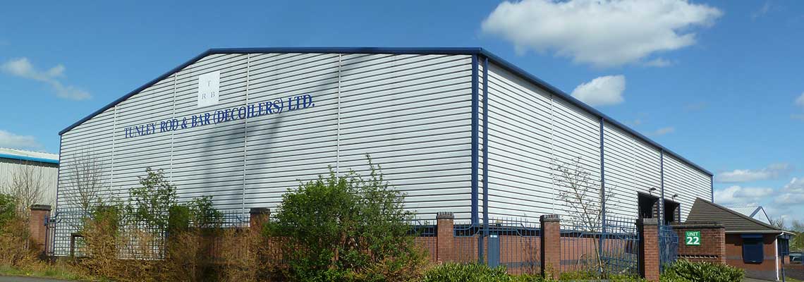
Tunley Rod & Bar (Decoilers) Ltd.
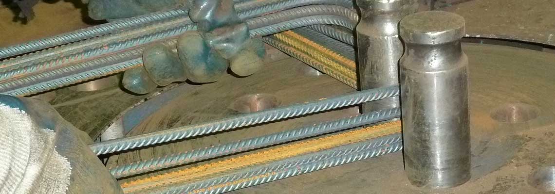
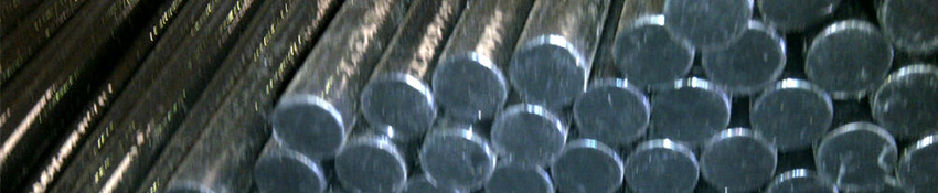
Sawn Dowel Bars
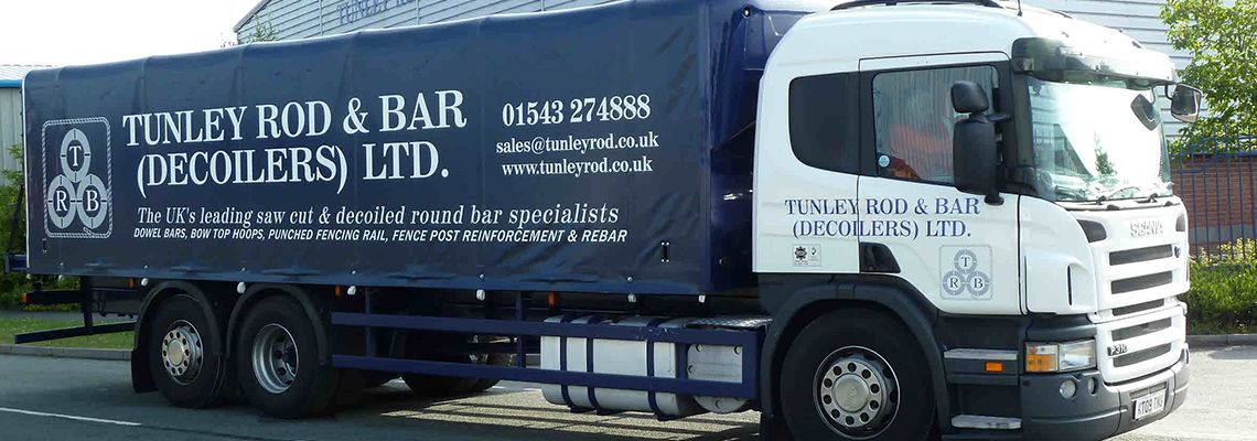
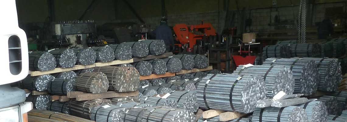
Probably the largest dowel bar manufacturer in the UK we are the main supplier to most major cut and bent reinforcement and construction product / accessory companies. Our next day pallet service has become invaluable to many of our customers knowing that they can rely on Tunley Rod & Bar to deliver the goods when and where they are needed.
Not only do we offer the full range of popular dowel bar sizes we can also offer bespoke lengths. Our dowel bars conform to BS 13877 part 3 as detailed in the Highways Agency Series 1000 Specification for Highway works Clause 1011 Dowel Bars.
Did you know that all dowel bars sold in the UK must be CE marked? Make sure that you conform to the law by buying only CE marked dowel bars from Tunley Rod & Bar.
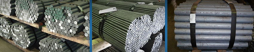
- Popular dowel bar sizes, saw cut and burr free!12mm: 300mm, 400mm, 450mm, 500mm, 600mm, 900mm, 1000mm
16mm: 300mm, 400mm, 450mm, 500mm, 600mm, 900mm, 1000mm 20mm: 400mm, 500mm, 600mm, 900mm
25mm: 400mm, 500mm, 550mm, 600mm, 650mm
32mm: 600mm 40mm: 600mm
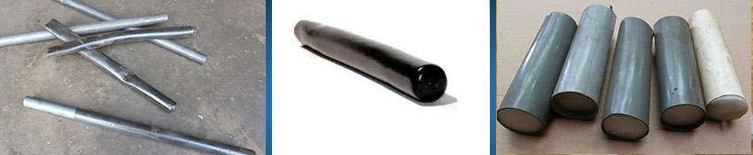
Polymeric Dowel Bars and Epoxy Coated Dowel Bars
We are the premier fusion bonded polymeric and epoxy coated dowel bar specialist in the UK. In accordance with the Highway’s Agency Series 1000, Clause 1011 specification our polymeric and epoxy coated dowels provide good anti-corrosion qualities complying with the specifications salt spray test in accordance with BS.EN ISO 9227:2006
Dowel Bars Sleeves and Caps
We carry a full range of dowel bar sleeves and caps which can be added on to you dowel bar orders for delivery direct to site, normally with no extra carriage charge.
Dowel Bar Sleeves manufactured from high grade flexible PVC which when slipped on to the end of a dowel bar creates a tough and durable debonded dowel joint. Dowel sleeves are sold in boxes of 100no.
- 12mm x 450mm, 16mm x 200mm, 16mm x 300mm, 16mm x 450mm
- 20mm x 300mm, 25mm x 300mm, 32mm x 375mm
Dowel caps 100mm long made from rigid plastic with a compressible filler at one end to allow for expansion, sizes to suite 12mm - 32mm smooth dowel bars and come in bags of 100no.
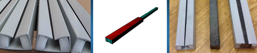
Square Dowel Bar & Sleeves (Permasleeve)
The “Permasleeve” dowel system can offer a benefits in certain areas over the more traditional round bar dowel bars normally used in contraction and expansion joints. Horizontal movement is facilitated by the use of two foam strips on each side of the sleeve but without allowing vertical any movement. This improves bending and shear resistance over a normal round bar dowel and the implications of misaligned dowels. The Permasleeve is 300mm long and accepts a 20mm square dowel. 600mm long normally, other lengths are available or cut to your requirements.
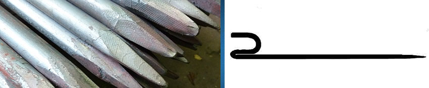
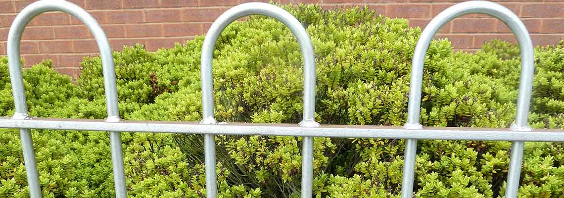
Line Pins, Fence Stakes, Geotex Hooks etc.
We supply a full range of pointed bars and pins, road pins, kerb pins etc. for various setting out uses, all the popular sizes or to your specification. We can also manufacture “J” hooks or “U” bars for holding down various things like GEOTEX® style matting or rabbit netting etc.