Tunley Rod & Bar (Decoilers) Ltd.
Steel Reinforcement For Concrete - BS 8666:2005 British Standard BS 8666 the 'Specification for scheduling, dimensioning, bending and cutting of steel reinforcement for concrete'. The previous standard (BS 4466) is also available for reference purposes. Table 1 - Radius Of Bending Radius of bending:- maximum values requiring bending
- Bar Size 6 8 10 12 16 20 25 32 40
- Radius (m) 2.5 2.75 3.5 4.25 7.5 14.0 30.0 43.0 58.0
Note. Bars to be formed to a radius exceeding the above dimensions will be supplied straight.
Table 2 - Minimum scheduling radii, former diameters and bend allowances
Nominal size of bar,
d
Minimum radius for
scheduling, r
Minimum diameter of
bending former, M
Minimum end projection, P
General (min 5d straight), including links where bend ≥ 150°
Links where bend < 150° (min 10d straight)
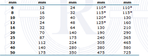
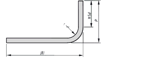
The minimum end projections for smaller bars is governed by the practicalities of bending bars.
- Note 1 Due to 'spring back' the actual radius of bend will be slightly greater than half the diameter of former.
- Note 2 BS 4449:2005 grade B500A in sizes below 8mm does not conform to BS EN 1992-1.1:2004.
- Table 3 - Standard shapes, their method of measurement and calculation of length
Method of measurement of bending dimensions Total length of bar (L) measured along centre line


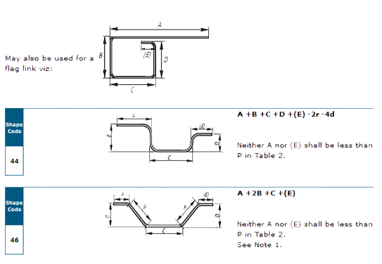


The values for minimum radius and end projection, r and P respectively, as specified in Table 2, shall apply to all shape codes (see 7.6).
The dimensions in parentheses are the free dimensions. If a shape given in this table is required but a different dimension is to allow for the possile deviations, the shape shall be drawn out and given the shape code 99 and the free dimension shall be indicated in parentheses.
The length of straight between two bends shall be at least 4d, see Figure 6.
Figure 4, Figure 5 and Figure 6 should be used in the interpretation of ending dimensions.
Note 1 The length equations for shape codes 14, 15, 25, 26, 27, 28, 29, 34, 35, 36 and 46 are approximate and where the bend angle is greater than 45°, the length should be calculated more accurately allowing for the difference between the specified overall dimensions and the true length measured along the central axis of the bar. When the bending angles approach 90°, it is preferable to specify shape code 99 with a fully dimensioned sketch.
Note 2 Five ends or more might be impractical within permitted tolerances.
Note 3 For shapes with straight and curved lengths (e.g. shape codes 12 13, 22, 33 and 47) the largest practical mandrel size for the production of a continuous curve is 400 mm. See also Clause 10.
Note 4 Stock lengths are available in a limited numer of lengths (e.g. 6m, 12m). Dimension A for shape code 01 should be regarded as indicative and used for the purpose of calculating total length. Actual delivery lengths should be by agreement with supplier.
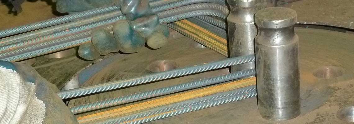
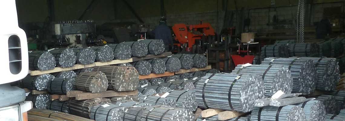
Specialists in plain round bar and reinforcing steel whether it be straight or bent, cropped or sawn make Tunley Rod & Bar (Decoilers) Ltd your first call!